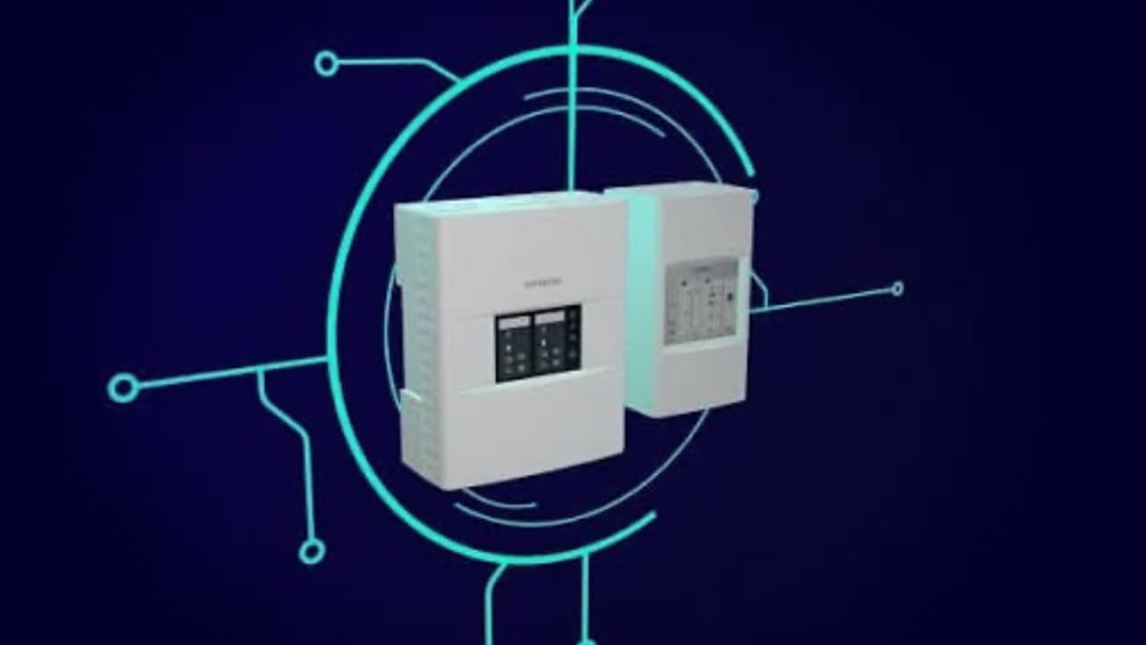
Aspirating smoke detection is the most sensitive fire detection most contractors ever work on, and the most dependent on being maintained properly. A point detector on a ceiling will keep doing roughly what it does with very little help. An aspirating system is a pump, a filter, a pipe network and a detection chamber working as one instrument, and every one of those parts degrades in a way that quietly moves the system away from what it was commissioned to do.
It is also where the money is. These systems protect data halls, switch rooms, cold stores, heritage interiors and process plant, which means the client is usually sophisticated, the downtime cost is high, and the service is valued. What clients will not tolerate is nuisance alarms, and nuisance alarms are almost always a maintenance problem rather than a design one.
This guide covers how aspirating detection actually works, the standards behind it, the airflow baseline that makes every later reading meaningful, what the routine service covers, transport time testing, why the pipe network must never be casually modified, the environment problems that drive false alarms, and how to price the work.
How an aspirating system works
Instead of waiting for smoke to reach a detector, an aspirating smoke detector goes and fetches the air. An aspirator draws a continuous sample through a network of pipes with precisely sized and positioned sampling holes, and passes it through a filter into a highly sensitive detection chamber, typically laser-based. Because it is continuously sampling and because the chamber is far more sensitive than a point detector, it can respond to the earliest products of combustion, often well before anything is visible.
Three consequences follow, and they explain almost everything about servicing:
- The pipe network is part of the detector. Its length, layout, hole sizes and hole positions were calculated to deliver a specific airflow and transport time. Change any of it and you have changed the detector.
- Airflow is the integrity mechanism. The system monitors flow to detect a blocked hole, a cracked pipe or a failing aspirator. That is why flow readings matter more than any other number in the service.
- The filter is a consumable in the truest sense: it is doing its job by getting dirty, and its condition directly changes what the chamber sees.
Commercial systems from the common manufacturers all work on those principles even though their terminology, alarm level naming and configuration software differ. The service discipline is the same; the specifics come from the manual for the product in front of you.
Where you find them, and why
| Environment | Why aspirating detection is used |
|---|---|
| Data halls and comms rooms | Very early warning before a fault becomes a fire, and high airflow that defeats point detection |
| Switch rooms and plant | Detection in spaces where a fire would be catastrophic and access is restricted |
| Cold stores and freezers | Point detectors perform poorly at low temperature; sampling pipe can be run where detectors cannot |
| High ceilings and atria | Sampling points can be placed at accessible heights rather than at an unreachable ceiling |
| Lift shafts and voids | Sampling avoids the access nightmare of servicing a detector in a shaft |
| Heritage interiors | Discreet: small sampling holes instead of visible detectors |
| Prisons and secure facilities | No accessible device in the protected space to be tampered with |
| Dusty or industrial areas | Filtration and adjustable sensitivity allow detection where point detectors would nuisance alarm |
Notice how many of those are chosen because the space is hard to access. That is a servicing cost, not a servicing saving. The detector is accessible; the sampling network usually is not.
The standards
- AS 1670.1 covers the design and installation of fire detection and alarm systems, including aspirating systems, and sets the performance the sampling network has to deliver, including transport time.
- AS 1851-2012 covers routine service of the detection and alarm system the aspirating detector forms part of.
- The manufacturer manual is more prescriptive than either on filters, flow tolerances, calibration status and configuration, and is what a reasonable technician is expected to follow.
- The system design documentation, produced by the manufacturer pipe modelling software, is the record of what the network was calculated to do.
That last item is the one that is missing on almost every established site, and it is the one that matters most.
The baseline that makes everything else meaningful
At commissioning, an aspirating system is normalised: the flow through each pipe is measured and recorded as the reference against which the system will judge itself for the rest of its life. Flow faults are deviations from that reference, not absolute values.
Here is the trap. When a technician replaces a clogged filter, flow rises. When a technician re-normalises the system after a change without understanding why the flow changed, the new reference locks in whatever condition the system was in at that moment. Do that a few times over a decade, without records, and the system is now measuring itself against a baseline that has nothing to do with its design.
Record the reference values and the date every time they are set, along with the reason. On a system with no commissioning data at all, record the absence as a non-conformance the same way you would for any other missing baseline, establish and document a reference set with the system in a known good condition, and tell the owner what happened and why it matters.
What the routine service covers
The detector and its environment
- Power, batteries and supply monitoring, and that the unit is in its normal state with no standing faults.
- The event and fault log since the last visit, which is the most informative thing on site and the most often skipped.
- Physical condition: mounting, cover, seals, and whether the ambient environment around the unit has changed.
- Configuration status: alarm thresholds, day and night settings, and any changes since the last visit.
Filters
Replace or inspect the filter according to the manufacturer requirement and the environment, not on a fixed habit. A data hall filter and a joinery workshop filter do not age at the same rate. Record the filter condition on removal, because a filter that is far dirtier than expected is evidence the environment has changed, and a filter that is spotless after a year suggests airflow is not reaching it.
Airflow
- Read and record the flow for every pipe, and compare to the recorded reference rather than to the tolerance band alone.
- Investigate any pipe that has drifted even within tolerance. A slow drift over three services is the early warning of a developing blockage or a leak.
- Where flow has increased, suspect a leak, a dislodged end cap, a broken pipe or a missing capillary.
- Where flow has decreased, suspect blocked sampling holes, a collapsed or crushed pipe, or a failing aspirator.
Smoke test and transport time
The functional test introduces an approved test aerosol or smoke source at the most remote sampling point and confirms two things: that the system responds and goes into the expected alarm state, and that it does so within the transport time the design requires. AS 1670.1 sets that limit, commonly 60 seconds from the most remote hole, with the design documentation confirming the figure that applies to the system in front of you.
A transport time that has lengthened since commissioning is one of the most useful diagnostics in fire detection. It usually means one of four things: sampling holes partly blocked, a pipe damaged or leaking, the aspirator losing performance, or somebody has extended the pipework. It is a measurement worth recording precisely rather than as a pass.
Alarm thresholds and the output side
- Confirm the alarm levels are as designed, and that any changes made since commissioning were authorised and documented.
- Prove the outputs: signals to the fire panel, brigade signalling, ancillary shutdowns and any interface to the building management system.
- Check day and night or occupancy-based sensitivity settings still match how the space is used, which changes more often than anyone tells you.
- Verify that fault conditions, particularly flow fault, actually report at the panel. A flow fault that nobody sees defeats the system integrity monitoring entirely.
The pipe network
- Inspect what you can reach: supports, joints, end caps, capillary drops and sampling points.
- Check sampling holes are clear, correctly sized and not painted over, and that identification labels are still legible.
- Look for anything new running near or through the network, and for signs the pipe has been used as a convenient support by another trade.
- Where the manufacturer procedure requires it, purge or clean the network, and record it.
The pipe network is not plumbing
This deserves its own warning, because it is the most common way a working system is quietly ruined. The sampling network is a calculated hydraulic design: pipe lengths, bends, hole sizes and hole positions produce a specific flow and transport time at each point. It is modelled in the manufacturer design software, and the output of that modelling is the design record.
Adding a metre of pipe to reach a new rack, drilling an extra hole over a new item of plant, capping off a branch during a fitout, or rerouting around a new wall all change the model. Any of them can push the transport time beyond the limit, starve the far end of the network, or make a sampling hole ineffective. None of them look like a big deal on site.
- Any change to the network needs to go back through the design model and be documented, not decided with a hacksaw.
- When you find an unauthorised modification, report it as a defect against the design, with a photograph and a location.
- After any authorised change, re-run the commissioning tests: flow, transport time, and a functional test at the new most remote point.
- Keep the design output with the site records, because without it nobody can say whether a modification was acceptable.
Environment, dust and the temptation to desensitise
Nuisance alarms on aspirating systems almost always trace back to the environment rather than the equipment, and the wrong fix is very tempting.
| Environment | What happens | The right response |
|---|---|---|
| Construction or fitout work | Dust drives repeated alerts and clogs filters in weeks | Formal isolation with a documented plan and an agreed end date, plus a filter change and a full test before reinstatement |
| Cold rooms and freezers | Condensation and ice in the pipe, and water in the detector | Check pipework falls, drains and any heated sections; look for water at the low points |
| Car parks and loading docks | Diesel and exhaust particulate reaching sampling points | Review thresholds against the design, check filter life, and discuss ventilation with the client |
| Workshops and warehouses | Sanding, cutting and forklift exhaust | Shorter filter intervals priced into the contract, not a sensitivity reduction |
| Kitchens nearby | Cooking aerosols drawn into the network | Check sampling point locations against the design and the current use of the space |
The wrong response to all of them is to quietly wind the sensitivity down until the complaints stop. That converts a very early warning system into an expensive ordinary one, and it does it in a way no one will notice until there is a fire. If the thresholds genuinely need to change, that is a design decision, made by someone entitled to make it, documented, and explained to the client in writing.
The defects you will actually find
| Finding | Likely cause | Why it matters |
|---|---|---|
| Flow fault on one pipe | Blocked holes, crushed pipe, dislodged end cap | Part of the protected area may not be sampled at all |
| Transport time longer than design | Partial blockage, leak, extended pipework or aspirator wear | Detection is slower than the design requires |
| Filter far dirtier than expected | Environment has changed since commissioning | Sensitivity drifts and the filter interval is wrong for the site |
| Thresholds altered with no record | Previous nuisance alarm addressed by desensitising | The system no longer performs as designed and nobody knows |
| Unauthorised pipe modification | Another trade extending or rerouting | The network no longer matches its model |
| Fault not reported at the panel | Output not connected, programmed or proven | The self-monitoring that justifies the technology is not working |
| No commissioning or design data | Lost through contractor and owner changes | Flow and transport results cannot be assessed against anything |
| Aspirator noisy or running slow | Bearing wear, end of service life | Progressive loss of performance across the whole network |
What to record at every visit
Aspirating systems reward record keeping more than any other detection technology, because almost every meaningful fault presents as a trend rather than a failure. A service record that says tested, no defects is worthless for that purpose. A good one is a data set.
- Flow reading for every pipe, as a number, alongside the reference value it is being compared against.
- Whether the system was re-normalised, when, and the documented reason.
- Filter condition on removal, and the date of the previous change.
- Measured transport time from the most remote sampling point, and which point that is.
- The alarm state reached during the functional test, and the time taken to reach it.
- Current alarm thresholds and day or night settings, recorded every visit so an unauthorised change is visible.
- Faults and events from the log since the last service, summarised, with anything recurring called out.
- Photographs of the detector, the filter and any accessible part of the network that has changed.
Three services of that data tell you things a single visit never will: that flow on pipe two has fallen four percent a year, that transport time has stretched by fifteen seconds since commissioning, that the filter is now lasting half as long as it did. Every one of those is a quotable piece of work identified before it became a fault.
Repair or replace?
Aspirating detectors have a supported life, and at some point the sensible advice to a client is replacement rather than another repair. The signals are consistent: the aspirator has been replaced once already, spares are on extended lead times, the configuration software no longer runs on a supported operating system, the chamber will not hold calibration, or the unit predates the current product generation by two iterations.
Raise it early and in writing, with a timeframe rather than an ultimatum. A data centre client given two years notice will budget for a staged replacement; the same client told during an outage that the part is unobtainable will remember who did not warn them.
Pricing aspirating work properly
- Price filters as consumables with an interval matched to the environment, and say so in the contract rather than absorbing them.
- Price the functional test realistically: reaching the most remote sampling point often means a ladder, a platform or an escort, and the test takes as long as the transport time allows, repeated.
- Allow for site access in critical environments: inductions, permits, change windows, escorts and out-of-hours attendance in data halls.
- Charge for investigating a flow fault as a separate attendance. Diagnosis in a ceiling void is not part of a routine visit.
- Quote network modifications as design work plus installation plus recommissioning, never as a labour hour.
- Plan for obsolescence. Detectors, aspirators and their configuration software have finite supported lives, and replacement is a project with a lead time, not a same-day swap.
Frequently asked questions
How often should an aspirating smoke detector be serviced?
The routine intervals come from AS 1851-2012 for the detection and alarm system, and the manufacturer manual sets additional requirements, particularly for filters. In dirty environments the filter interval is driven by the environment rather than the calendar, and should be agreed with the client and written into the contract.
What is transport time and what is the limit?
It is the time taken for smoke entering the most remote sampling hole to reach the detector and produce a response. AS 1670.1 sets the requirement, commonly 60 seconds for the most remote point, and the system design documentation confirms the figure that applies to a given installation.
Can we add a sampling point to cover a new rack or machine?
Not without re-modelling the network. Hole sizes and positions are calculated, and adding one changes the flow and the transport time everywhere else. Treat it as a design change: model it, install it, then recommission and retest.
The system keeps alerting during a tenant fitout. What should we do?
Isolate formally, with a documented plan, an agreed end date and the responsible entity aware, and consider interim detection arrangements for the space. Then change the filter and run a full functional test before reinstating. What you should not do is reduce sensitivity and forget about it.
We replaced the filter and the flow changed. Do we re-normalise?
Yes, that is exactly the situation re-normalising is for, provided you record what you did and why. What you must not do is re-normalise around a flow change you cannot explain, because that hides a fault rather than fixing it.
There is no commissioning data for the system. Can we still service it?
Yes. Service it, record the absence of commissioning and design data as a non-conformance, establish a documented reference set with the system in a known good condition, and tell the owner what that means: until the design data is recovered or re-created, nobody can say whether current performance matches what was installed.
Is aspirating detection worth it for the client?
Where the asset or the consequence justifies very early warning, yes, but only if it is maintained. A neglected aspirating system with a clogged filter, a blocked branch and thresholds wound down to stop complaints offers less protection than a well-maintained conventional system, at several times the price.
Sources and further reading
- AS 1670.1 Fire detection, warning, control and intercom systems: System design, installation and commissioning, Standards Australia
- AS 1851-2012 Routine service of fire protection systems and equipment, Standards Australia
- Good practice guide for the inspection, testing, maintenance and repair of fire protection systems in NSW buildings, Building Commission NSW (January 2026)
- FSG-05 Maintenance of fire protection systems and equipment, ACT Fire & Rescue (August 2023)